

NEMA 17 Radial and Axial Load Limits: Bearing Life, Belt Tensioning, and Mechanical Sizing Guide
Calculate NEMA 17 radial and axial load demands, check belt tension and bearing-life limits, and use a practical supplier checklist. Request a load review.
Content Integrity Note
- Author: Carl Ostermann - Principal Electromagnetic Drive Specialist
- Published: 2026/10/27
- Basis: Factory-side NEMA 17 OEM communication and validation workflows.
- Boundary: Final model and parameter decisions should be validated in your own system tests.
NEMA 17 radial and axial load limits are model-specific. A 42 mm frame size or a holding-torque value does not establish how much belt force or leadscrew thrust its bearings can carry. Confirm the load direction, application point, speed, and duty against the selected motor's mechanical specification before approving a design.
Published and reviewed: October 27, 2026. Scope: global OEM engineering and procurement of NEMA 17 hybrid stepper motors. SI units are used, with source units retained where useful. The examples below are reproducible calculations, not motor tests, warranty statistics, or certified load ratings. Integrated linear actuators and gearheads require their own output-bearing specifications.
1. Executive Summary & Scope
- Size torque and bearing loads separately. A motor may deliver enough torque while its shaft loading exceeds the mechanical rating.
- Measure the load position. A radial rating without its distance datum is incomplete.
- Include installation tension. A belt loads the bearings before the motor starts.
- Keep thrust in a defined load path. Check push and pull directions separately, particularly on vertical leadscrews.
- Approve the complete assembly. Bearing catalogue capacity alone does not establish the limits of the shaft, endbells, retention, lubricant, or finished motor.
For a design review, send your load diagram and operating conditions to our application team. Include pulley position and belt tension rather than only the required holding torque.
2. Anatomy of the NEMA 17 Mechanical Assembly
A motor's front and rear bearings support its rotor and shaft. NSK's deep-groove bearing overview confirms that this bearing type can carry radial forces and axial forces in both directions. The assembled motor may impose lower limits through its shaft, housing, fits, preload, or retention.
Conceptual load-path diagram, not a section drawing or a statement of internal dimensions. Scroll horizontally on small screens. Actual bearing positions and preload arrangements must come from the selected supplier.
Front and rear bearing reactions
For a simplified shaft with two ideal radial supports, let the bearing centers be separated by distance b, with radial force Fr applied distance a outside the front bearing. Static equilibrium gives front reaction magnitude Rf = Fr × (1 + a/b) and an opposite rear reaction of magnitude Rr = Fr × a/b. The front reaction can therefore exceed the external force; the rear bearing participates in carrying the moment. These equations omit housing compliance, preload, and other forces.
Preload, retention, and internal clearance
Some motors use a wave washer or another preload arrangement. Its location and retention determine whether axial push and pull have different limits. Do not infer spring force, allowable endplay, or rotor-stator clearance from the NEMA frame designation. A radial magnetic air gap is not an allowable axial displacement specification.
3. Calculating Dynamic Radial (Overhung) Load
Torque-driven force versus total bearing load
The tangential force needed to transmit torque is Ft = T/r, with torque T in N·m and pitch radius r in meters. Use operating and acceleration torque at the actual speed; holding torque is not an available running-torque guarantee.
For a spur gear, tooth separation adds a radial component. For a belt, installation tension adds forces that do not disappear at zero torque. The shaft force is the vector sum of span forces, component weight, and other applied loads. Supplier transmission and service factors can support screening, but they must not replace a load diagram or be applied twice to the same load.
Oriental Motor's sizing guide explains why static belt tension, dynamic forces, and the load application point all need checking against the motor specification.
Belt installation tension: an explicit worked example
Assume a 20-tooth pulley with 2 mm pitch, two parallel spans pulling in the same direction at 180° wrap, equal span stiffness, and negligible centrifugal effects:
- Pitch diameter:
Dp = 20 × 2 / π = 12.73 mm; radiusr = 0.006366 m. - Assumed peak operating torque:
T = 0.50 N·m. - Required tension difference:
T1 − T2 = T/r = 78.54 N. - Assumed installation tension per span:
T0 = 45 N. - Under the equal-stiffness approximation:
T1 = 84.27 NandT2 = 5.73 N. - Shaft radial demand:
Fr ≈ T1 + T2 = 90 N, including at rest when both spans carry 45 N.
T0 ≥ Ft/2 only keeps the idealized slack-span tension nonnegative. It is not a sufficient tooth-engagement or belt installation specification. Belt width, tooth engagement, span geometry, dynamics, and the belt manufacturer's tensioning method still matter.
If this 90 N force acts at the Lin 4118 published load point described below, it is about 3.37 times that series' 26.7 N radial limit. That comparison rejects this example at the published point; it does not predict how many hours the bearing will last.
| Assumed tension per span at rest (N) | Calculated shaft radial force (N) | Engineering interpretation |
|---|---|---|
| 10 | 20 | Installation load only; verify running span tensions |
| 15 | 30 | Installation load only; verify running span tensions |
| 20 | 40 | Installation load only; verify running span tensions |
| 25 | 50 | Installation load only; verify running span tensions |
| 30 | 60 | Installation load only; verify running span tensions |
| 40 | 80 | Installation load only; verify running span tensions |
| 45 | 90 | Worked-example installation setting |
All seven rows use Fr = 2 × T0 for the stated parallel-span geometry. They are calculated demands, not allowable motor loads or recommended belt tensions; lower tensions may be unable to transmit the example torque.
Measure installation tension using the belt supplier's force-deflection or frequency method. A frequency reading needs the correct span length and belt mass per length; a pitch heard by ear is not a transferable tension specification.
4. The Fulcrum Effect: Distance-Based Derating
For radial force Fr acting distance a outside the front bearing center, the bending moment at that support section is M = Fr × a. If the force is dimensioned from the mounting face, add the supplier's internal face-to-bearing distance to obtain a.
As a purely geometric example, assume that internal distance is 5 mm and Fr = 30 N. Moving the force from 5 mm to 15 mm outside the face changes a from 10 mm to 20 mm and doubles the section moment from 0.30 to 0.60 N·m. This does not establish a derated permissible force: bearing spacing, shaft geometry, housing stiffness, and the manufacturer's acceptance criteria are still needed.
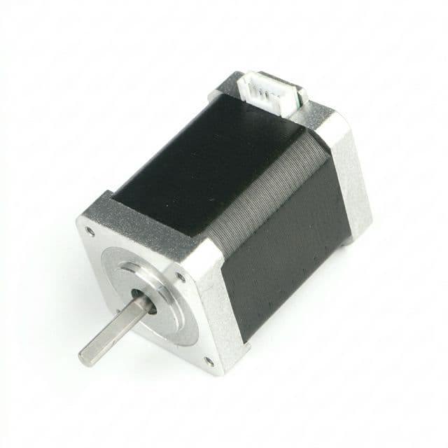
Mount a pulley close to the face while preserving required clearances. Ask for an allowable-load curve if your load position differs from the published point; do not extrapolate an undocumented universal NEMA 17 derating table.
5. Published Load Example and Mechanical Sizing Decisions
The Lin Engineering 4118 series operating specifications provide a concrete NEMA 17 example. Values below were checked on October 27, 2026 and apply to that series, subject to the supplier's conditions:
| Published item | Source value | SI conversion / meaning |
|---|---|---|
| Maximum radial load | 6 lbf | Approximately 26.7 N |
| Radial-load position K, from mounting face | 0.620 in | 15.75 mm |
| Maximum axial load | 6 lbf | Approximately 26.7 N; confirm push/pull conditions |
| Maximum case temperature | 176°F | 80°C |
| Ambient temperature | −4°F to 122°F | −20°C to 50°C |
| Magnet-wire insulation | Class B, 130°C | Winding classification; not a grease limit |
The listed limits do not supply a combined-load envelope or a guaranteed motor lifetime. Request confirmation when radial and axial loads act together, when shocks or reversals occur, or when the operating point differs. A longer motor stack may improve torque without changing its bearing-load limit.
Use this decision matrix to compare architectures without inventing ratings from motor length:
| Configuration | Load or constraint to establish | Procurement decision |
|---|---|---|
| Short or pancake motor | Actual bearing arrangement and shaft overhang | Obtain model-specific limits before compact packaging approval |
| Longer high-torque motor | Increased transmitted force and unchanged bearing design | Check mechanical ratings independently of holding torque |
| Timing-belt direct drive | Installation and running span-force vectors | Compare load and position against the motor drawing |
| Spur-gear or pinion drive | Tangential and separating forces | Evaluate shaft bending and both bearing reactions |
| Vertical leadscrew | Gravity, acceleration, process thrust, and reversal | Specify which bearing block carries screw thrust |
| Custom bearing arrangement | Fits, preload, thermal expansion, and assembly validation | Require a supplier drawing and load test plan |
| Separately supported drive shaft | Support reactions and alignment | Route belt or gear loads through a designed shaft assembly |
| Integrated gearbox | Output radial/axial limits at the actual lever arm | Approve the exact gearhead, ratio, speed, and duty |
For a missing load curve or combined-load limit, request the mechanical specification with your RFQ before treating the design as approved.
6. Bearing Fatigue Life and Thermal Limits
What basic rating life can establish
For ball bearings under the assumptions of the basic rating-life model:
L10 = (C/P)^3 in millions of revolutions.
At constant nonzero speed n in rpm:
L10h = [1,000,000 / (60 × n)] × (C/P)^3 hours.
C is the selected bearing's basic dynamic load rating. P is its equivalent dynamic bearing load, derived from the bearing reactions, axial load, and catalogue factors. It is not automatically the external pulley force. For combined loads, use the exact bearing supplier's applicable X, Y, and threshold factors; generic miniature-bearing constants are insufficient.
L10 is a statistical fatigue rating associated with 90% survival under the model's conditions, not a promise that an installed motor will reach that life. Doubling P reduces the calculated ball-bearing fatigue life to one eighth if all other inputs stay constant. Increasing P by 25% gives 1/1.25^3 = 0.512 of the baseline. Exceeding a motor's permissible shaft force by 25% does not automatically imply that same life ratio.
Use the NSK technical-calculation workflow with the exact supported bearing designation, and have the motor supplier confirm reactions, preload, and conditions. No absolute service hours are assigned here because those inputs are unavailable. Basic rating-life arithmetic does not establish static indentation resistance, shock capacity, lubricant life, seal life, or accuracy retention. Near standstill or with oscillatory motion, also review static loading, fretting, and the applicable supplier method.
Temperature and lubricant selection
Review the motor case limit, actual ambient conditions, bearing operating temperature, grease specification, speed, and sealing together. Winding insulation class does not authorize bearings or grease to operate at that temperature. Request a temperature-rise test under representative current, speed, enclosure, and duty. Do not apply a universal grease-life halving rule or specify a named grease without checking bearing and application compatibility.
7. Mechanical Architectural Mitigations
Mitigation 1: A separately supported drive shaft
When direct mounting exceeds the motor's documented limit, mount the pulley or gear on a shaft with suitably sized bearings attached to the machine frame, then transmit torque through a suitable coupling. Adding a bearing directly to the motor shaft instead needs an alignment, fit, thermal expansion, and reaction-load review: extra support can overconstrain the existing bearings and does not guarantee a fixed percentage capacity increase.
Mitigation 2: A gearbox with documented output bearings
A gearbox may address both speed reduction and output-load requirements, but torque multiplication is not proof of radial or thrust capacity. Check its exact shaft-load table, load distance, backlash, efficiency, mounting, and duty before selection.
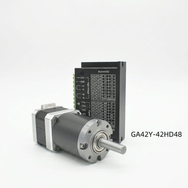
Configuration image only; no load rating or test result is inferred from the pictured assembly.
Mitigation 3: Leadscrew thrust carried by the machine frame
Use a correctly sized fixed bearing block or other designed thrust support to route screw thrust into the chassis. Select the remaining support arrangement to permit required thermal movement. Size the coupling for torque, speed, allowable misalignment, and axial reaction. A flexible coupling alone is not a thrust-isolation device. Purpose-built motor-integrated linear actuators can be suitable when their thrust ratings cover the application. For a vertical axis, also evaluate power-loss holding and braking.
Mitigation 4: A different motor or frame size
A larger frame or different bearing arrangement is an option when it has documented capacity at the required load point. Recheck driver compatibility, inertia, running torque, speed, mounting, and thermal behavior. Frame size alone does not prove a particular radial or axial limit.
8. NEMA 17 Mechanical Procurement & Factory Audit Checklist
Use the checklist as an RFQ and sample-acceptance framework. Agree numerical tolerances with the supplier for the actual application rather than treating them as universal NEMA requirements.
Bearing traceability and thermal conditions
- Identify the exact motor revision, bearing designation, supplier, seals or shields, and lubricant specification.
- Confirm bearing clearance, fits, preload, and retention against thermal expansion; do not mandate C3 clearance without the bearing supplier's calculation.
- Record ambient range, case-temperature limit, speed, duty cycle, orientation, and target service life.
- Require the supplier to distinguish bearing-fatigue calculations, lubricant estimates, and measured motor endurance results.
Mechanical drawing and load approval
- Dimension the pulley or gear force center from the supplier's stated mounting-face or bearing datum.
- Submit radial and axial force directions, static values, peak values, duration, reversals, and simultaneous-load cases.
- Obtain push/pull limits, allowable overhang, and any combined-load or shock restrictions in writing.
- Specify shaft diameter and fit, runout, pilot concentricity, endplay, and their measurement locations and applied test forces.
- Agree shaft material, hardness, pulley retention, and installation method; do not transmit pressing or hammering forces through the bearings.
Sample validation and production acceptance
- Measure installed belt tension, shaft runout, endplay, temperature rise, and vibration under representative duty.
- Define sample count, test duration, force/speed profile, inspection method, and acceptance thresholds before testing.
- Retain the approved drawing, supplier load confirmation, sample results, and a production change-control requirement.
9. Frequently Asked Questions (FAQ)
What is the maximum permissible radial load for a standard NEMA 17 stepper motor?
There is no universal NEMA 17 load rating. Lin Engineering lists 6 lbf (about 26.7 N) at 0.620 in (15.75 mm) from the mounting face for its 4118 series. Use the exact motor model, load position, and operating conditions for approval.
Why can overtightened GT2 timing belts damage NEMA 17 motor bearings?
Installation tension loads the shaft even at zero torque. With two parallel belt spans pulling in the same direction, 45 N per span produces about 90 N radial load. This is a calculation example, not a measured failure-life prediction; follow the belt and motor suppliers' limits.
What happens if axial thrust exceeds the motor's specification?
Excess thrust can overload bearings, change preload, or move the rotor, depending on the bearing retention design. Push and pull limits may differ. A radial air-gap dimension does not establish allowable axial travel; request both directional limits and the specified endplay test.
Can a standard NEMA 17 motor directly drive a vertical Z-axis leadscrew?
Only if the motor or actuator is rated for the actual thrust and duty. Otherwise, route screw thrust into a bearing block attached to the machine frame. A flexible coupling accommodates specified misalignment but does not by itself isolate axial thrust. Evaluate load holding and braking separately.
How does motor temperature affect bearing life and load capacity?
Temperature changes lubricant viscosity and useful grease life. Check the actual bearing, grease, speed, ambient temperature, and motor case limit together. Winding insulation class is not a bearing grease rating, and a basic fatigue-life calculation is not a complete motor service-life prediction.
When should an engineering team switch from direct drive to a planetary gearbox?
Consider a gearbox or separately supported shaft when direct drive cannot meet the documented load-position limit or required torque and speed. Check the exact gearbox output-bearing ratings, backlash, efficiency, and duty; no single force threshold applies to every NEMA 17 assembly.
10. Submit a Mechanical Load Review Request
When contacting NEMA17Motor about an OEM motor program, include the motor envelope, shaft drawing, pulley pitch diameter and position, installation tension, torque/speed profile, radial and axial loads, temperature, and duty. Ask for written load limits and a sample-validation plan for the proposed configuration.
Send your mechanical specification and RFQ to discuss motor, shaft, bearing-support, or gearbox options. Confirm availability, drawings, acceptance criteria, and delivery terms in the quotation.
For related motor-selection topics, browse the NEMA 17 engineering blog.
Sources and Further Reading
Sources checked on October 27, 2026. Manufacturer specifications apply to the identified products and stated conditions; calculations in this article are explicitly labeled examples.
- Oriental Motor — Motor Sizing Basics Part 4: How to Calculate Radial Load and Axial Load: Load direction, application distance, belt-tension checks, and transmission-factor screening. The article's geared-motor examples are not NEMA 17 ratings.
- Lin Engineering — 4118 Series: Operating-specification values used in Section 5. No universal NEMA 17 load or lifetime claim is inferred.
- NSK — Deep Groove Ball Bearings: Bearing type and radial/axial load capability. This overview does not establish the finished motor's shaft-load limit.
- NSK — Technical Calculations: Entry point for designation-specific bearing life and fit calculations, not a tested life result for the motors shown here.
Author

Carl Ostermann - Principal Electromagnetic Drive Specialist
Principal Electromagnetic Drive Specialist specializing in high-torque-density motor topologies, slotless/frameless stator-rotor thermal management, and industrial motion control.
More Posts
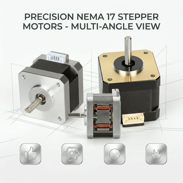
NEMA 17 Integrated Motors: BOM Reduction & TCO Analysis for OEMs
Learn how integrated NEMA 17 stepper motors reduce BOM complexity and TCO for OEMs, with sourcing checks, TCO inputs, and RFQ questions for global buyers.
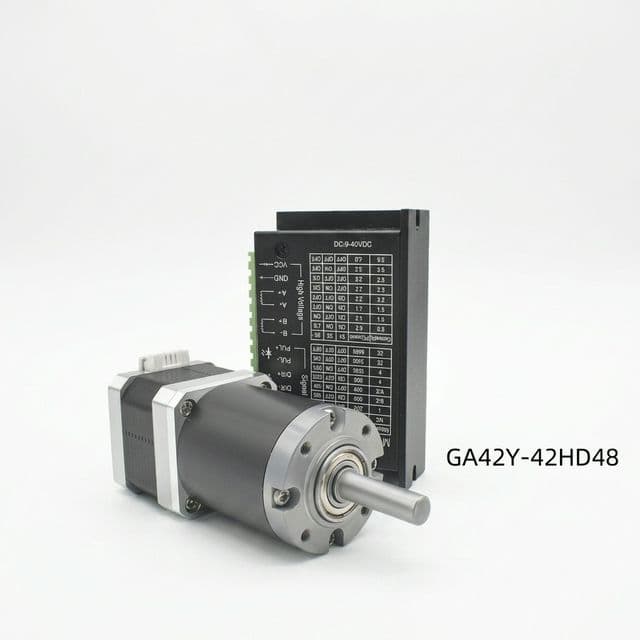
NEMA 17 Customization: Shaft, Connector, Gearbox, and Lead Screw
What OEM buyers should define early when requesting customized NEMA 17 assemblies for production programs.
NEMA 17 Compliance & Digital Traceability: 2026 Procurement Guide
Prepare NEMA 17 stepper motor compliance files for CE, RoHS, and emerging Digital Product Passport expectations with a practical RFQ checklist.