1. What you can decide now
Select a flange class, then a model
42mm narrows the mounting envelope. It leaves shaft, connector and winding choices open. Compare the released drawing before reusing a bracket. [S1]
Request torque at your speed
Static holding torque cannot approve a moving axis. Ask for a matching motor-and-driver curve. [S2]
Treat electrical screening as a filter
Pulse and I²R arithmetic can reveal conflicts, but cannot prove current tracking, temperature or position accuracy. Current waveform quality matters. [S3]
Keep supply and board limits explicit
Raising voltage requires a compatible driver, board and supply design. An IC headline current is not a guaranteed module continuous current. [S4]
2. Stack choices: what remains unknown
This is an engineering comparison framework, not a tested product ranking. The calculator presets demonstrate arithmetic across five body-length classes; no manufacturer performance or price is implied. Procurement guidance below is an engineering recommendation, not a measured benchmark.
| Candidate envelope | Reason to investigate | Cost / integration tradeoff | Running torque / price |
|---|---|---|---|
| 20–25mm pancake | Short axial space or low moving mass | May need gearing or a lower acceleration target | N/A — request model and curve / quote |
| 34mm compact | Compact feeder or light positioning stage | Verify duty cycle before accepting smaller packaging | N/A — model-specific |
| 39–40mm standard | General-purpose axis candidate | Compare winding and connector options | N/A — model-specific |
| 47–48mm long body | Investigate extra torque in the same flange class | Check mass, axial clearance and rotor inertia | N/A — model-specific |
| 58–60mm extra-long | Evaluate when a shorter candidate fails at load | Compare gearbox or larger-frame alternatives | N/A — model-specific |
A public drawing can supply static specifications while leaving dynamic suitability unknown. Keep those columns separate:
| Quantity | Published drawing | Selection limit |
|---|---|---|
| Body / phase data | 39.3mm maximum; 1.50 A/phase; 2.00 Ω ±10%; 3.90 mH ±20% | Phase-current convention must be reconciled with the driver setting |
| Holding torque | 0.42 N·m = 42 N·cm | Static quantity; not running torque |
| Available torque at 300 RPM | N/A — curve not supplied on this drawing | Obtain a matching curve or measurement |
[S1] The example is an external reference, not a claim about our stock or a substitute for a supplier-approved specification.
3. Mechanical fit: square spacing, model-specific depth
Do not label the 31mm square mounting pattern as a 31mm pitch-circle diameter. Check the pilot, shaft, axial projection, thread engagement, connector clearance and coupler fit on the exact drawing. A generic ISO fit class does not establish a motor supplier’s tolerance.
Thread-depth boundary: the reference drawing marks hole depth as 4.5 MIN. It does not define a universal maximum screw penetration. Obtain the supplier’s permissible engagement and account for the assembled bracket thickness. Do not use the housing as a thread-depth gauge. [S1]
4. Reproducible calculation method and limits
| Output | Calculation | Assumption / excluded effect |
|---|---|---|
| STEP frequency (Hz) | RPM × (360 / step angle) × external divisor / 60 | Does not include controller scheduling overhead or pulse-width requirements |
| Electrical time constant (ms) | L (mH) / R (Ω) | Connected winding; R and L vary with temperature and measurement conditions |
| Sine copper loss, both phases total (W) | Ipeak² × R | IA = Ipeak sin θ; IB = Ipeak cos θ; equal phase R. Core and driver losses excluded |
| Both phases at full peak DC (W) | 2 × Ipeak² × R | An alternative waveform case, not extra loss added to the sine case |
| 50% sine hold-current copper loss (W) | (0.5 × Ipeak)² × R | Same resistance and waveform; not total heat or a guarantee of sufficient holding torque |
| Static resistive drop (V) | Ipeak × R; ratio = Vbus / (Ipeak × R) | Excludes L di/dt, back-EMF, switching drops and supply transients |
| Torque margin (%) | (supplied running torque − required torque) / required torque × 100 | One operating point only; N/A at zero load or when curve torque is unknown |
The sine-loss expression follows from summing the two phase losses: R(IA² + IB²). Sine/cosine excitation is described in [S3]. The displayed microstep increment is a command increment; it is not guaranteed shaft displacement. Ideal incremental torque is sin(90°/M) relative to ideal full-step holding torque, not the motor’s total torque.
Missing a current rating or curve? Request an engineering review5. Match current, wiring and pulse generation
| Decision | Required check | Action if unknown |
|---|---|---|
| Peak versus RMS | Use the same phase-current convention for motor allowance and driver setting | Ask supplier; do not automatically multiply a catalog A/phase value by √2 |
| 4-, 6- or 8-lead connection | Use R, L and permitted current for the actual connected phase | Obtain wiring diagram; isolate unused leads; never connect/disconnect while powered |
| 0.9° versus 1.8° | 0.9° doubles external pulse demand at equal RPM and divisor | Compare actual curves; do not infer high-speed torque from angle alone |
| TMC2209 supply example | IC operating range is 4.75–29V; board limits may be lower | 36V/48V needs a suitably rated alternative, not this IC |
| Interpolation | Use the external STEP divisor, not the internal interpolated subdivision | Read mode/configuration and verify pulse width and timing |
Current matching affects actual motion [S3]. Driver-specific electrical limits and STEP configuration must come from the relevant manual [S4]. The tool’s driver maximum is user supplied; it is not automatically tied to a named driver.
6. Running torque, acceleration and resonance
Ask for the curve at your voltage, winding connection, phase current and driver mode. Enter the available torque at the requested shaft speed, then include acceleration and friction in required torque. Recording a source makes the comparison auditable; it does not authenticate the point. [S2]
Holding
At rest. Useful for stationary load checks; not a substitute for a running curve.
Pull-in
Start/stop envelope. Attached inertia changes it; no universal safe direct-start RPM is asserted.
Pull-out
Running envelope. A point inside it still requires a suitable acceleration and deceleration path.
A 150–250 RPM “safe/unsafe” map would imply evidence this page does not have. Sweep the planned speed range under load, identify vibration or lost-step regions, and tune the motion profile. For a vertical axis, test power-loss restraint separately; a motor or encoder alone is not a fail-safe brake.
7. Copper loss is not a temperature prediction
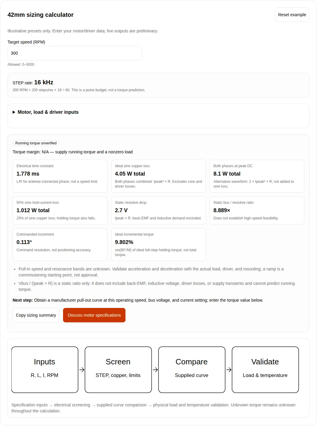
At the default illustrative 1.5A peak and 1.8Ω, ideal sine loss is 4.05W for both phases combined. Half that current gives 1.0125W at unchanged R. Both phases simultaneously at full 1.5A DC would instead dissipate 8.1W. These waveform cases must not be mixed.
Core and driver switching losses, hot-winding resistance, mounting heat flow, ambient and duty cycle are outside the model. Do not infer a universal safe case temperature from insulation class. Log steady-state temperature and check the exact motor, bearing, cable and driver limits. Standstill-current control exists on drivers such as TMC2209, but its setting needs validation for the application. [S4]
8. Three worked screening scenarios
All cases below are hypothetical calculations, not customer deployments or measured performance. They use the default example except where stated. Reset the calculator before each case.
A. Pulse-limited axis
Set 600 RPM, 0.9°, 1/32 and a 100kHz controller limit. Demand is 600 × 400 × 32 / 60 = 128kHz, so a conflict appears.
Reduce to 1/16 for 64kHz, then check controller pulse timing and running torque. Passing the pulse check does not approve the axis.
B. One-point torque comparison
At 300 RPM, enter 30 N·cm and an explicitly illustrative reference against a required 20 N·cm. Arithmetic margin is (30 − 20) / 20 = 50%.
The source remains user supplied. Replace it with a real matched curve, include acceleration demand, and validate the duty cycle.
C. Stationary holding check
Set 0 RPM. Pulse demand becomes 0Hz while modeled sine copper loss remains 4.05W; reducing sine current to 50% gives 1.0125W.
Check the remaining holding torque before lowering idle current. A vertical load may require independent restraint.
9. Risks, alternatives and the minimum next test
| Risk / trigger | Consequence | Mitigation / alternative |
|---|---|---|
| Misuse: treat preset or holding torque as a running curve | Missed steps or an undersized axis | Request matched dynamic evidence; test acceleration and load together |
| Electrical: peak/current convention or supply mismatch | Overheating or driver damage | Reconcile conventions and board ratings; measure transients before raising voltage |
| Cost: select the longest stack by default | Added moving mass, space and integration expense | Compare shorter motor plus transmission; include gearbox backlash and maintenance in the quote |
| Scene mismatch: long screw, incompatible shaft or connector | Assembly damage or rework | Approve drawing, screw engagement and harness pinout before ordering |
| Motion: inertia or resonance not represented by one curve point | Unreliable starts, stops or reversals | Tune ramps; test full speed sweep; consider feedback or a different motor/drive class |
| Thermal / gravity: reduce hold current without a load check | Lost holding capacity or uncontrolled movement | Test stationary torque and temperature; evaluate independent brake/restraint |
10. Evidence register and known gaps
Published . Sources reviewed . NEMA17Motor publishes and reviews this guide every six months.
Sources checked on 2026-10-31. Recheck in six months or when the chosen motor drawing, driver revision or supplier specification changes. Engineering calculations are identified separately from published specifications. No prices, stock availability, universal tolerances or measured preset torque curves are claimed.
[S1] STEPPERONLINE 17HS15-1504S drawing
One-page drawing, dimensions and specification block; drawing dated 2019-03-04.
One named 39mm-class motor: mounting geometry, R/L, phase rating and static holding torque. No running curve is supplied on this drawing.
Checked 2026-10-31. Source scope does not establish all-model performance.
[S2] Oriental Motor: Speed–Torque Curves for Stepping Motors
Curve conditions and definitions 1–14; web article, no publication date shown.
Running curves depend on the motor/driver combination. Pull-in depends on attached inertia; holding torque is a standstill quantity.
Checked 2026-10-31. Source scope does not establish all-model performance.
[S3] TI SLOA293A: How to Improve Motion Smoothness and Accuracy of Stepper Motors
Revised October 2021; §2.2.1, Figure 2-1 and Table 2-1.
Sine/cosine phase currents, current-matching errors and ideal incremental torque. It does not provide a universal 42mm torque curve.
Checked 2026-10-31. Source scope does not establish all-model performance.
[S4] Analog Devices / Trinamic TMC2209 datasheet, Rev. 1.09
2023-02-16; front-page ratings, §1.7, §9, §13 and electrical characteristics.
Supply/current limits, standstill current control and external STEP versus internal interpolation. Board limits and cooling must also be checked.
Checked 2026-10-31. Source scope does not establish all-model performance.
Still needed for your hardware: an exact part number, released mechanical drawing, permitted current convention, matching running curve, actual inertia/friction, supply transient measurements and thermal data. If these are missing, export the preliminary summary and request them; no feasible-system verdict is available.
11. Selection questions by decision type
Frame and selection
Is a 42mm stepper motor the same as NEMA 17?
42mm is commonly used for this flange class. It does not specify the winding, shaft, body length or running torque. Check the exact mechanical drawing rather than assuming complete interchangeability.
Does a longer body guarantee more useful torque?
No. It is a candidate-selection dimension. Compare the required speed, winding, driver, rotor inertia and actual curve; a longer motor may also add moving mass.
What mounting screw depth should I use?
Use the exact model drawing and supplier instruction. The cited example says 4.5 mm minimum hole depth; this is not permission to insert a screw arbitrarily far, and it is not a universal maximum engagement. Account for bracket and washer thickness.
Calculator and evidence
Are the five presets measured motor specifications?
No. They are hypothetical input examples for comparing calculations. They carry no manufacturer running-torque data. Enter the exact motor values and obtain a matching curve before selecting hardware.
Why is running torque unverified by default?
Frame size, resistance and inductance cannot establish a running-torque curve. The optional comparison uses a point and reference supplied by you; the calculator cannot authenticate the source or approve the system.
Does a positive torque margin mean the axis is ready?
No. The comparison covers one supplied point. Include friction, acceleration, transmission losses and uncertainty, then test the full motion cycle and thermal behavior. A zero load has no defined percentage margin.
Drive and current
Should I enter peak or RMS current?
The tool uses phase peak for both the permitted motor value and driver setting. For sinusoidal current, peak equals square root of two times RMS. A catalog phase-current rating may use a different convention; confirm it before conversion.
Can I run a TMC2209 from 36V or 48V?
No. The cited IC datasheet states a 4.75–29V operating range. Module components or thermal design may impose lower limits. Select a driver explicitly rated for the supply and its transients.
Will 256-step internal interpolation multiply controller pulse demand?
Use the external STEP divisor in this calculator. Internal interpolation refines driver current generation; it does not mean the controller must send every interpolated microstep.
Thermal and motion limits
Does 50% idle current cut total heat by 75%?
It cuts the modeled copper component to 25% at unchanged resistance and waveform. Core, switching and driver losses are excluded. Verify that the reduced holding torque can restrain the load.
What is the universal safe direct-start RPM?
There is none. Pull-in behavior depends on the motor, driver, current, supply and attached inertia. Start with a conservative ramp and test starts, stops and reversals with the actual load.
Does more microstepping guarantee better accuracy?
No. It refines command resolution. Current errors, load deflection, friction and motor nonlinearity affect actual position. Validate accuracy or use appropriate position feedback when needed.