Select a motor, not just a frame
Check the part drawing, winding data and load curve. A frame size does not define output. [6]
Published · Reviewed · By NEMA17Motor
A 2-phase NEMA 17 motor has two winding phases in a roughly 42 mm mounting frame. Use this planning tool to calculate STEP rate, winding loss and curve-based load checks before selecting a motor and driver.
Check the part drawing, winding data and load curve. A frame size does not define output. [6]
Six-lead full/half coil and eight-lead series/parallel are different electrical configurations. [1]
Holding torque describes standstill. Use the curve for the chosen drive conditions. [2]
Higher command resolution costs pulse bandwidth; verify actual motion under load. [4]
Phase A and B are driven by separate H-bridges. The frame name identifies a mounting family around 42 mm square; it leaves electrical and shaft details to the particular motor. The example below is one catalog item, not a family specification. [6]
| Property | Example value | Selection use |
|---|---|---|
| Frame / body | 42.3 mm square × 38 mm body | Check bracket, shaft and connector clearance against its drawing. |
| Step angle / leads | 1.8° / four leads | 200 full steps/rev; bipolar drive. |
| Winding data | 1.65 Ω; 3.2 mH per coil | Example L/R ≈ 1.94 ms. |
| Current | 1.68 A per coil in detailed specifications | Confirm excitation and current convention before setting a driver. |
| Holding torque | 36 N·cm in the manufacturer PDF | Standstill rating. Seller rounds this to 3.7 kgf·cm; use the manufacturer PDF for design. |
SOYO manufacturer drawing and test curve (PDF) specifies 31 mm mounting-hole spacing on a square, a 22 mm pilot and 4.5 mm M3 hole depth for this part only. Its curve uses 24 V, 1.68 A and half stepping; match those conditions before using it.
Use this topology map with the motor’s own diagram. Power off and discharge the supply before changing connections. The calculator requires connected-phase ratings and makes no automatic winding conversions. [1] [3]
| External leads | Available bipolar connection | What to verify |
|---|---|---|
| 4 leads | One complete phase per H-bridge | Identify the two isolated coil pairs and rated current. |
| 6 leads | Full coil, with each center tap isolated | Use end-to-end R/L and the full-coil current rating. |
| 6 leads | Half coil, using one end and its center tap | Insulate the unused ends; use half-coil ratings. No bipolar parallel option. |
| 8 leads | Series or parallel half windings | Confirm paired windings, polarity and manufacturer connection ratings. |
A series connection generally has higher inductance than parallel for the same reconnectable winding. Published multipliers depend on the reference connection; they cannot be applied to an unrelated four-lead motor.
Identify coil pairs with a meter →The pulse counts below are arithmetic, not performance measurements. Choose the motor using its load curve and measured positioning behavior. [4] [5]
| Dimension | 1.8° motor | 0.9° motor |
|---|---|---|
| Full steps per revolution | 200 | 400 |
| External STEP pulses per revolution | 3,200 | 6,400 |
| STEP input frequency | 16 kHz | 32 kHz |
| Commanded mechanical increment | 0.1125° | 0.05625° |
| Actual positioning accuracy | Unknown without loaded measurement | Unknown without loaded measurement |
| Running torque | Needs its motor/driver curve | Needs its motor/driver curve |
At 1/16 stepping, the ideal torque associated with a one-microstep displacement is sin(90°/16) ≈ 9.8% of the full-step holding torque. This local restoring-torque relationship does not mean running torque is 9.8% of the motor rating. [4]
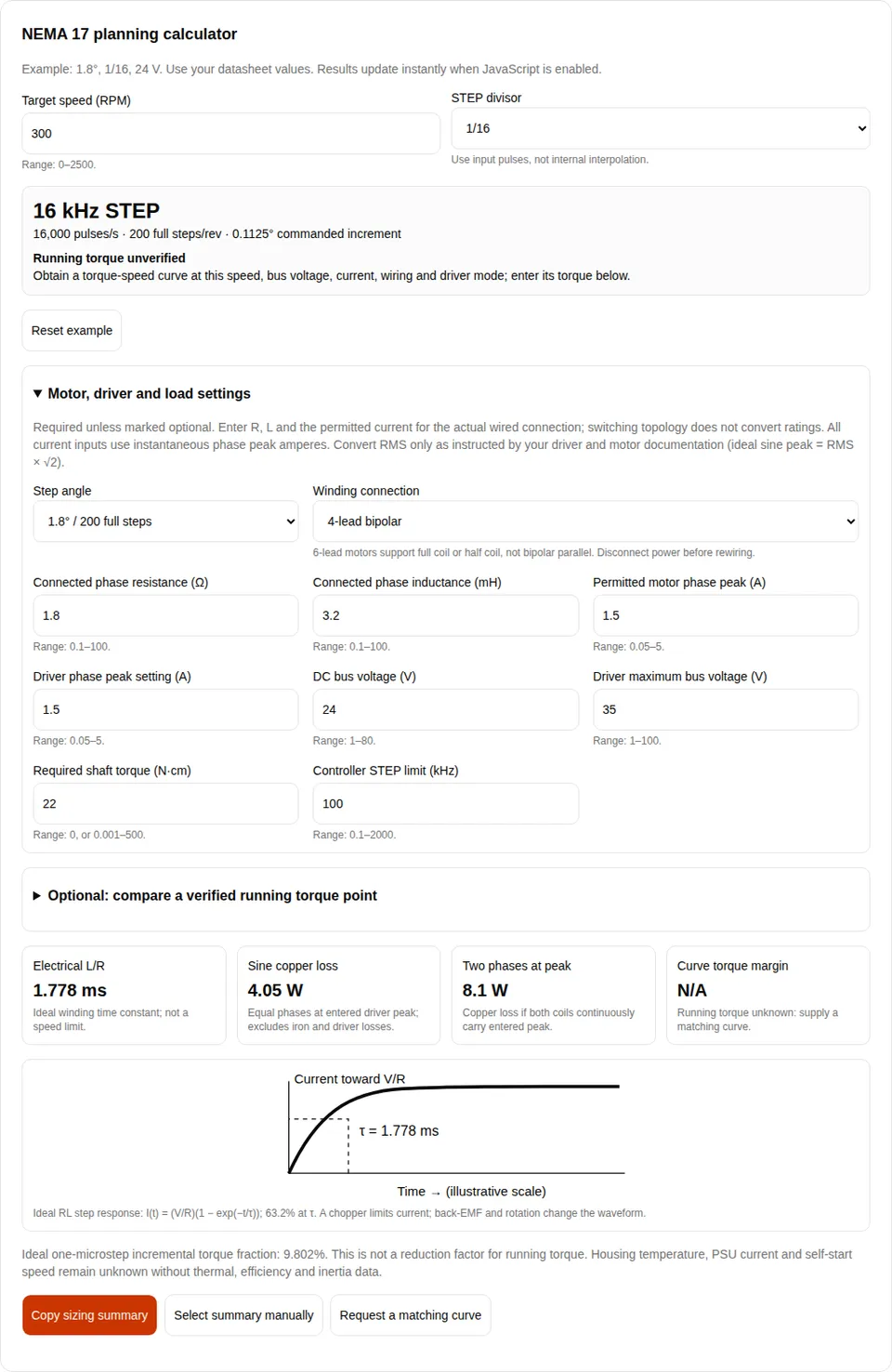
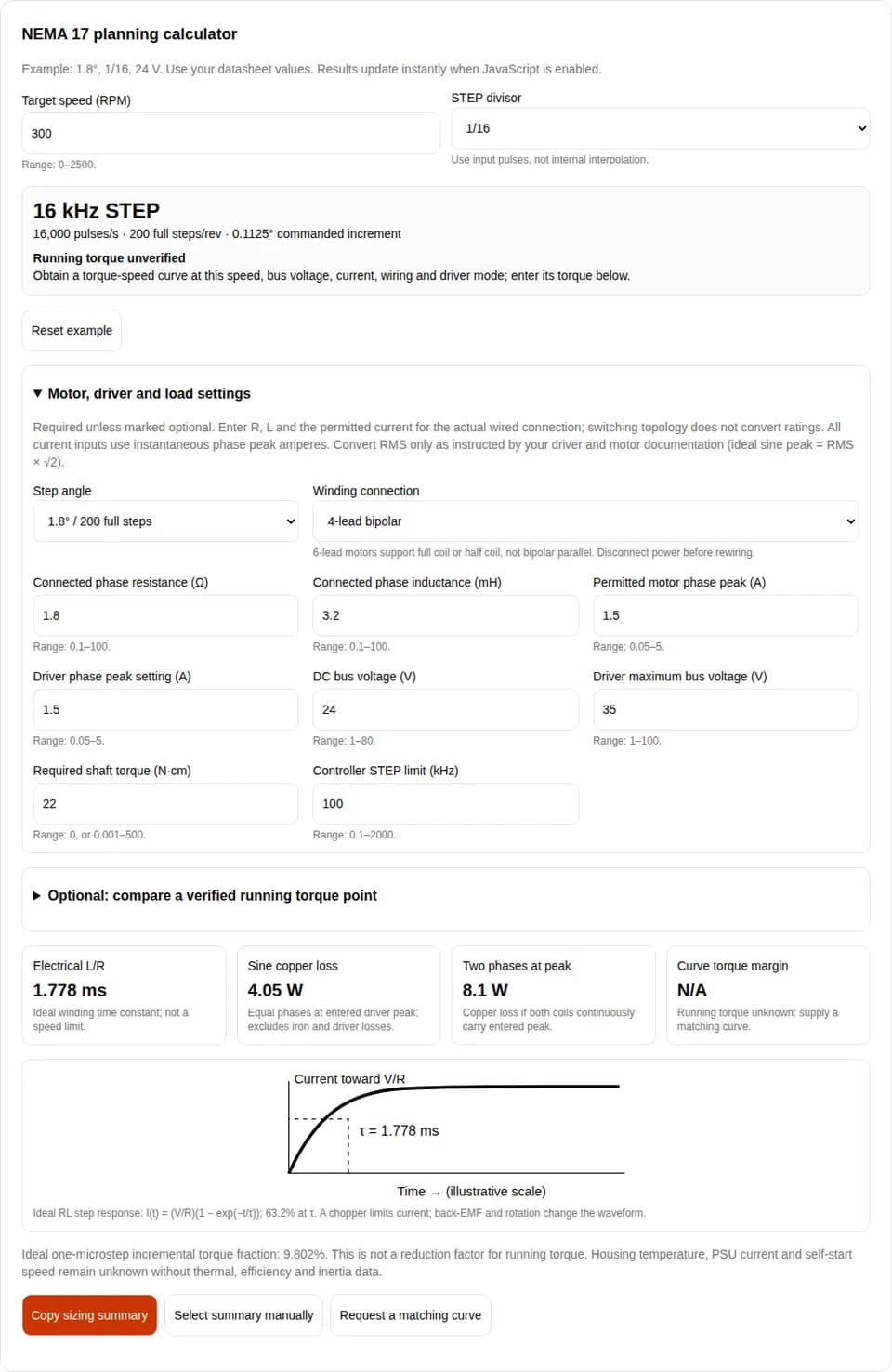
The following equations are engineering identities or explicitly idealized models. Inputs remain user-supplied; positive outputs are not a safety approval. Calculations update synchronously, without network requests.
| Output | Method | Limit |
|---|---|---|
| STEP frequency | f = RPM × (360 / step angle) × M / 60, in Hz | M is the external input divisor, not driver interpolation. |
| Electrical time constant | τ [ms] = L [mH] / R [Ω] | Ideal RL winding. Does not establish a knee speed or back-EMF constant. |
| Sine copper loss | P = Ipeak² × R, in W | Two equal phases, ideal sine/cosine currents at entered driver peak; R at its measurement temperature. Excludes iron and drive losses. |
| Both phases at peak | P = 2 × Ipeak² × R, in W | Different excitation assumption: both coils continuously at entered peak. Not a temperature prediction. |
| Curve torque margin | (Tcurve − Trequired) / Trequired × 100% | Only for supplied matching curve data and positive required load. Zero load gives N/A. |
| Housing temperature / PSU current | Unknown | Requires measured losses, heat transfer, efficiency, duty and electrical demand. |
| Pull-in speed / running torque prediction | Unknown | Requires drive-specific curves, load inertia and motion testing. |
Current basis matters: an ideal sinusoid has Ipeak = √2 × Irms per phase. A motor’s catalog “A/phase” or a driver’s full-step measurement may use a different convention. Confirm both documents before entering the permitted motor peak.
Request the curve and current conventionA torque-speed curve belongs to a specific motor, driver, supply and connection. Pull-out torque describes running capability; starting with load inertia requires a separate check. The tool compares one supplied point and does not synthesize a curve. [2]
For the A4988 Black Edition example, Pololu specifies an 8–35 V bus; this is not a recommendation to run at the upper limit. The board’s cooling and current-setting instructions apply to that carrier. [3]
| Check | Evidence needed | If missing |
|---|---|---|
| Driver current | Peak/RMS convention and continuous board rating at actual cooling | Start from a documented conservative setting; confirm phase current. |
| Bus voltage | Driver, capacitors and supply ratings including transients and regeneration | Do not raise voltage until every rating is checked. |
| Temperature | Motor winding, case and magnet limits; mounting, ambient and duty test | Measure a representative thermal soak. Copper loss alone cannot determine housing temperature. |
| Shaft / pilot / screw fit | Exact drawing: dimensions, tolerances, usable shaft and thread engagement | Request the drawing; do not assume a universal 4.5 mm screw depth or ISO fit. |
| Body length | Space, mass, winding data and curve for each candidate | Treat length as packaging, not a torque specification. |
Standstill current reduction may reduce copper loss, but also reduces holding capability. Verify the load first; vertical axes may need an independent brake or counterbalance. An insulation-class winding limit is not a housing touch-temperature rating.
Illustrative arithmetic, not tested machine results or product recommendations. Use the tool defaults unless stated otherwise.
At 300 RPM, 1.8° and 1/16, the controller must generate 16,000 STEP pulses/s. Switching to 0.9° doubles that to 32,000.
Next: compare the configured pulse limit and pulse timing. Running torque remains unverified until a matching curve is supplied.
R = 1.8 Ω and Ipeak = 1.5 A gives 4.05 W for ideal sine/cosine excitation, or 8.10 W if both phases continuously carry 1.5 A.
Next: confirm excitation and cooling, then measure temperature. Neither number determines a housing temperature or PSU rating.
Assume a matching measured curve gives 30 N·cm at 300 RPM and the required torque is 22 N·cm. Margin = (30 − 22)/22 = 36.4%.
Next: enter the curve reference and test the acceleration envelope. The assumed 30 N·cm is not a claim about a catalog motor.
| Situation | Risk / cost | Mitigation or alternative |
|---|---|---|
| Using holding torque at travel speed | Lost position or stall despite adequate standstill torque | Obtain the matching curve; reduce speed/load or compare gearing. |
| Increasing supply voltage | Driver damage from ratings or transients | Check all component limits; choose a suitable driver rather than applying a generic 36/48 V remedy. |
| Increasing current or stack length | Heat, moving mass, cooling and enclosure cost | Compare winding losses, mass and measured cycle performance. |
| Adding a gearbox | Backlash, efficiency loss, noise and packaging cost | Include gearbox input inertia and losses; check output precision. Ideal reflected load inertia is Jload / ratio². |
| Open-loop with costly missed steps | No direct confirmation that commanded motion occurred | Evaluate encoder feedback or closed-loop control. Feedback does not create unlimited torque. |
| Sustained speed beyond available curves | Unknown torque reserve and thermal behavior | Request tested data or compare another frame size, servo or BLDC with a suitable transmission. |
Links and stated scopes checked 2026-10-31. This is an editorial engineering guide with illustrative calculations, not an independently certified motor test. Prices and availability are excluded; follow the latest exact-part documentation when ordering. NEMA17Motor reviews this guide every six months and when source documentation changes.
6-lead full/half coil; 8-lead series/parallel. Conversion factors use the catalog’s stated unipolar reference, not an arbitrary 4-wire motor.
Holding, pull-in and pull-out torque; curve conditions and load inertia. Does not validate a universal knee RPM or startup speed.
This board’s 8–35 V range, current setting, cooling and power-disconnection precautions. Other carriers require their own documentation.
Commanded resolution, positioning limits and incremental torque. Additional commands do not guarantee corresponding shaft motion.
Sections 2.2.3–2.2.4: incremental torque, current accuracy and load margin. Revision October 2021; no universal thermal model is inferred.
One specific 42.3 mm-square, 38 mm-long, 200-step motor; dimensions and winding ratings are model-specific.
The formulas and examples identify what can be computed from the supplied inputs. Public sources do not validate a universal NEMA 17 thermal resistance, curve shape, mounting fit or self-start speed; those remain part-specific.
Two phase describes the two independently driven winding phases. NEMA 17 describes the mounting frame family, roughly 42 mm square. It does not specify current, holding torque, length or driver compatibility. See the model example and source register above.
Not with its normal external leads: each phase has a shared center tap. Use full coil with the center tap insulated, or half coil with the unused end insulated. True bipolar parallel requires separately accessible half windings, normally an eight-lead motor. Follow the manufacturer diagram.
Do not transfer wire colors between suppliers. With power disconnected, identify continuity and center taps, then confirm winding polarity against the motor diagram before connecting a driver.
No. Obtain the exact motor drawing and its permitted thread engagement. Subtract bracket and washer thickness from screw length; the resulting penetration must fit that drawing. NEMA 17 alone is not evidence for a universal depth or fit tolerance.
A suitable current-regulated chopper can operate above the winding’s DC I×R voltage. Its bus-voltage rating, current convention, protection, wiring and cooling must all be checked. The winding voltage alone does not approve the power supply.
No. A switching driver changes voltage and current between the supply and winding. Size the PSU using measured electrical demand, drive losses, simultaneous axes, acceleration and regeneration. The calculator deliberately does not infer a supply current from phase current.
At the same external microstep divisor, a 0.9° motor needs twice as many STEP pulses per revolution as a 1.8° motor. Compare actual torque-speed curves and loaded positioning performance; there is no universal 500 or 600 RPM crossover.
No. Startup depends on pull-in behavior, load and rotor inertia, friction and the drive. Obtain the applicable start/stop data, program an acceleration profile and test with the real mechanism. A single running torque point does not establish startup capability.
Resistance, inductance and holding torque cannot uniquely identify running torque for every motor and driver. Enter a curve point with matching test conditions to compare load, or request that curve using the inquiry section.
No. It is a comparison at one steady-speed operating point using data you supplied. Allow for friction, acceleration, current accuracy, supply variation and resonance; validate the complete motion cycle and thermal soak.
Percentage margin divides by required torque, so zero load has no defined percentage. Pulse rate, time constant and copper loss still calculate. Add realistic friction and acceleration torque before evaluating load margin.
It increases commanded resolution and can smooth motion. Friction, load, detent torque and current errors limit realized positioning. The ideal one-microstep incremental torque fraction is not a multiplier for running torque.
Copy your tool summary and include the part number, connection diagram, torque-speed target, acceleration, load inertia, duty, ambient and mounting drawing. Ask for the matching curve and current-setting convention before approval.