NEMA 17 Hybrid Linear Stepper Actuators: External vs. Non-Captive vs. Captive Sizing & Procurement Guide
Compare NEMA 17 linear actuators: External, Non-Captive, and Captive. Check thrust, backdriving, duty cycle, and backlash; prepare an OEM RFQ with clear inputs.
Content Integrity Note
- Author: Carl Ostermann - Principal Electromagnetic Drive Specialist
- Published: 2026/10/29
- Basis: Factory-side NEMA 17 OEM communication and validation workflows.
- Boundary: Final model and parameter decisions should be validated in your own system tests.
NEMA 17 linear stepper actuators combine a hybrid stepper with a lead screw or rotor nut to simplify compact linear motion. Choose External when a guided nut or carriage should travel along a rotating screw; Non-Captive when a restrained screw can translate through the motor; and Captive when built-in output-rod anti-rotation suits the required stroke. Check load, speed, heat, and power-off behavior before approving a model.
Published and reviewed: October 29, 2026. Scope: global OEM engineering and procurement of NEMA 17 hybrid linear stepper actuators for laboratory automation, optical positioning, dispensing, and assembly. NEMA 17 identifies a nominal frame family, not a force, stroke, or accuracy rating; check the actual mounting drawing (suppliers may describe this family as 42 or 43 mm).
Basis and limits: This is a supplier-document comparison with reproducible engineering calculations, not a hardware test or customer case study. Numerical examples are explicitly assumed and do not qualify an actuator, medical device, or load-holding system. Final requirements depend on the exact assembly and operating environment.
1. Executive Summary & Kinematic Architecture Selection
Choosing an integrated linear stepper requires matching physical movement constraints to the three fundamental mechanical architectures:
- External (EXT): The screw rotates with the rotor and an external nut travels axially. Restrain nut rotation with the carriage or another guide. Confirm the screw-to-rotor connection, thrust-bearing capacity, and whether the free end needs support.
- Non-Captive (NC): A nut inside the rotor drives a screw through the motor. Prevent screw rotation while allowing translation, and reserve space for its full travel on both sides of the motor.
- Captive (CPT): An internal anti-rotation mechanism keeps the output rod from turning. It can simplify a short-stroke push/pull axis; side loads and overturning moments may still require external guidance. Stroke and rear clearance are model-specific.
These three configurations are documented on the Haydon Kerk Size 17 product page; verify dimensions for the selected part number.
       ACTUATOR ARCHITECTURE SELECTION RULE

  Need built-in output-rod anti-rotation?
  ├── YES ──> Check captive stroke, side load and envelope
  └── NO  ──> Can the screw translate through the motor?
              ├── YES ──> NON-CAPTIVE; constrain screw rotation
              └── NO  ──> EXTERNAL; constrain traveling nut rotation
For custom screw lengths, specialized thread pitches, or anti-backlash nut prototyping, contact our linear engineering team with your axial load profile and stroke requirements.
2. Mechanical Kinematics & Force Vector Diagram
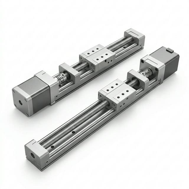
The conceptual schematic below shows which member moves and where anti-rotation is needed. It is not a mounting drawing, dimensional specification, or bearing-support design:
3. Mechanical Sizing Physics: Thrust, Speed, and Lead Conversion
The fundamental advantage of an integrated hybrid linear stepper is direct rotary-to-linear conversion without mechanical coupling compliance. Sizing relies on three core physical relationships:
3.1 Linear Thrust vs. Motor Torque
Linear thrust force F (in Newtons) is governed by available motor dynamic torque T (in N·m), screw lead P_lead (in meters per revolution), and thread efficiency η:
F = (2 × π × T × η) / P_lead
Where:
T: Available motor torque at operating step frequency (N·m). Obtain the running torque or direct force-speed curve for the chosen motor, winding, driver, current, and supply. Holding torque does not establish running thrust.P_lead: Linear advancement per complete 360-degree revolution. Note: For multi-start screws, Lead = Pitch × Starts. An 8 mm diameter 4-start screw with 2 mm pitch has an 8 mm lead (P_lead = 0.008 m).η: Mechanical thread efficiency; use supplier data for the specific lead, nut, lubrication, load, and speed.
3.2 Positional Resolution
For a standard 1.8-degree two-phase stepper motor (200 full steps per revolution), the baseline full-step linear resolution is:
Resolution (full-step) = P_lead / 200
Under microstepping drivers (e.g. 1/16 or 1/32 microstepping):
Resolution (microstep) = P_lead / (200 × microstep_factor)
A 1.0 mm lead screw operated at 1/16 microstep yields a theoretical step resolution of 0.3125 μm. This is a command increment, not measured accuracy or repeatability. Lead error, backlash, load deflection, friction, and microstep nonlinearity affect actual motion.
3.3 Linear Velocity
Linear speed V (in mm/sec) is dictated by motor rotational speed N (in RPM) and lead P_lead (in mm):
V = (N × P_lead) / 60
3.4 Worked Lead Comparison: Six Illustrative Screw Options
For a transparent comparison, assume the same 0.10 N·m running torque at 300 RPM for every row. Efficiencies below are illustrative inputs, not measured material properties or supplier ratings. Apply F = 2πTη / P_lead with lead converted to meters. The 600 RPM column gives kinematic speed only; it does not establish available thrust or permitted operating speed.
| Illustrative thread option | Nominal diameter | Lead per rev | Starts | Assumed efficiency | Calculated thrust at 300 RPM | Kinematic speed at 600 RPM | Selection question |
|---|---|---|---|---|---|---|---|
| Tr8x1 | 8 mm | 1.00 mm | 1 | 20% | 125.7 N | 10 mm/s | Is fine travel worth the higher RPM? |
| Tr8x2 | 8 mm | 2.00 mm | 1 | 30% | 94.2 N | 20 mm/s | Does it meet the required speed and force? |
| Tr8x4(P2) | 8 mm | 4.00 mm | 2 | 40% | 62.8 N | 40 mm/s | Is reversal error within budget? |
| Tr8x8(P2) | 8 mm | 8.00 mm | 4 | 60% | 47.1 N | 80 mm/s | How will a vertical load be restrained? |
| 1/4-20, single-start | 6.35 mm | 1.27 mm | 1 | 25% | 123.7 N | 12.7 mm/s | Is this exact thread form compatible? |
| Custom high-lead example | 6.35 mm | 4.88 mm | Supplier-defined | 45% | 57.9 N | 48.8 mm/s | Can the supplier document the complete thread? |
For example, 2 × π × 0.10 × 0.30 / 0.002 = 94.2 N. This excludes separately specified preload drag and other losses outside the thread efficiency. The usable assembly force is bounded by the motor curve, nut load rating, bearings, screw strength, and thermal limits. Do not transfer thread codes between suppliers or treat 1/4-20 as interchangeable with metric trapezoidal or proprietary threads.
For the drive inputs needed before using this equation, see NEMA 17 torque, current, and driver matching.
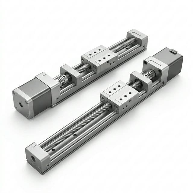
Layout illustration only; the image does not verify internal actuator construction, dimensions, or rated performance.
4. The Critical Boundary: Self-Locking vs. Backdriving
Vertical assemblies can move under gravity during power loss. Assess holding behavior independently of powered thrust; neither nominal frame size nor fine lead establishes safe holding.
4.1 Lead-Angle Screening
For a simplified square-thread model, compare lead angle λ with friction angle:
tan(λ) = P_lead / (π × d_m)
Self-locking is predicted only when tan(λ) < μ_s within that model. Here d_m is the pitch diameter and μ_s the actual static friction coefficient. Trapezoidal thread flank angle changes the effective friction relationship; use the supplier's thread model for an actual design.
As a sensitivity example, a 2 mm lead and assumed 7 mm pitch diameter give tan(λ) = 0.091, or about 5.2°. Assuming μ_s = 0.12 predicts static self-locking in the simplified model; assuming μ_s = 0.06 predicts backdriving. These are hypothetical friction inputs, not measured POM properties. The same lead can therefore produce different conclusions.
4.2 Power-Off Holding Requirements
Lubrication, wear, temperature, vibration, and shock can change behavior. Obtain a supplier backdriving assessment and test the actual orientation, payload, and environment. A fine lead, motor detent torque, or an unpowered driver is not a validated load-holding device. Where uncontrolled descent creates a hazard, specify a suitably rated brake, counterbalance, or independent restraint through the machine's risk assessment.
5. Duty Cycle, Nut Heating, and PV Limits
There is no universal 10%–20% duty-cycle assumption or fixed thrust derating percentage for NEMA 17 actuators. The Haydon Kerk Size 17 page explicitly labels performance curves at 100% duty cycle with defined drive conditions. Check the exact curve and assembly rather than borrowing a percentage from another product.
5.1 Pressure-Velocity Screening
Lead screw sliding friction produces heat at the nut interface. The screening relationship is:
PV = p_contact × v_sliding
p_contact is contact pressure, not simply axial force divided by screw cross-section; v_sliding is thread contact sliding velocity, not carriage velocity. Ask the supplier to evaluate the selected nut geometry, material grade, lubrication, and temperature. Generic POM or PEEK labels do not establish a numerical PV limit or continuous thrust rating.
Thomson's application note, PDF pages 3 and 6, explains how load, speed, and heat interact. Its application guidance is not a substitute for the exact actuator's operating envelope.
5.2 Specify the Complete Operating Cycle
Report moving duty as t_motion / (t_motion + t_dwell). For example, 2 seconds moving and 8 seconds dwelling is 20% moving duty. Record travel direction, acceleration, load, ambient temperature, and hold-current settings: an energized stationary motor can still heat the assembly during dwell.
Before approving continuous use, request force-speed data under the proposed drive conditions, a thermal-soak test at the worst operating cycle, and an agreed wear/endplay limit. If only intermittent data are available, treat continuous capability as unresolved rather than applying a generic 0.35 or 0.50 multiplier. If the operating conditions are not yet defined, request an actuator sizing review with the proposed load and motion cycle.
5.3 Lubrication and Coatings
Select lubricant or dry coating with the nut supplier. Confirm compatibility, particle shedding, cleaning chemistry, and maintenance interval. A PTFE coating alone does not establish cleanroom suitability, vacuum compatibility, sterilization resistance, or medical approval. These environments need their own material and assembly qualification.
6. Backlash: Standard vs. Preloaded Nuts
Backlash is lost axial motion when direction reverses before the opposing thread flank carries load. It differs from lead accuracy, elastic compliance, and the commanded microstep increment.
A standard nut may suit a mechanism whose load consistently seats the same flank. For frequent bidirectional positioning, consider an anti-backlash design and specify allowable lost motion under a stated reversing load, temperature, and wear condition. Do not assume every standard nut has the same clearance or every preloaded nut achieves less than 5 μm.
Preload removes clearance by loading opposing contact surfaces. Depending on the design, it also adds drag and heat; request drag torque and stiffness data rather than applying a universal efficiency penalty. If the applied reversing force overcomes the take-up mechanism, lost motion may return. Test the loaded mechanism over its intended life, not just an unloaded first sample.
Thomson's lead screw range includes standard and anti-backlash nut options. Procurement should identify the exact nut construction and acceptance method before comparing quotations.
7. Column Buckling and Critical Speed
7.1 Compression Buckling Calculation
A long screw under compression can bow before motor thrust is exhausted. For an ideal straight elastic column:
F_crit = π² × E × I / (K × L)²
E: Young's modulus; assume193 GPafor this stainless-steel example.I = π × d_root⁴ / 64: Area moment based on screw root diameter, not nominal diameter.L: Actual unsupported length at the worst travel position, in meters.K: Effective-length factor: 2 for fixed-free, 1 for pinned-pinned, approximately 0.699 for fixed-pinned, and 0.5 for fixed-fixed ideal end conditions.
Worked example: with assumed d_root = 6.2 mm, L = 200 mm, and fixed-free support (K = 2), I ≈ 7.25 × 10^-11 m⁴ and F_crit ≈ 864 N. An illustrative factor of 3 would reduce that ideal-column screening value to about 288 N; this is not an actuator load rating. Initial curvature, mounting flexibility, thread geometry, yield, eccentric loading, and the supplier's design margin remain to be checked. A motor bearing cannot automatically be treated as an ideal fixed support.
A screw tip support changes the boundary conditions only if its mounting actually provides the assumed restraint. See NEMA 17 radial and axial bearing-load limits before assigning the entire screw load to the motor bearings.
7.2 Rotating-Screw Critical Speed
An External screw's unsupported span and end supports limit permissible rotational speed. Obtain the supplier's critical-speed calculation and operating margin for the actual assembly. A coarser lead reduces RPM for a required linear speed but also changes force, resolution, and backdriving behavior. A properly restrained translating Non-Captive screw does not have the same rotating-shaft whirling mechanism, although compression buckling still requires review.
8. Worked Application Scenarios — Not Tested Case Studies
Scenario A: Laboratory Syringe-Pump Sizing
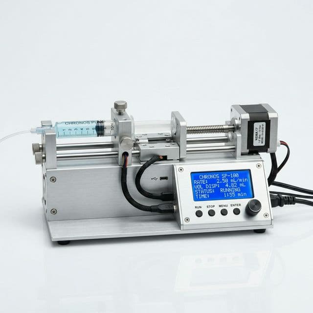
Application illustration only; it does not establish a Non-Captive internal construction or medical performance.
Assume a syringe with a 10 mm internal bore, a 1.27 mm screw lead, a 200-step motor, and 1/16 microstepping. The nominal command increment is 1.27 / (200 × 16) = 0.000396875 mm. Multiplying by the bore area gives π × 10² / 4 × 0.000396875 = 0.0312 μL per command increment, using 1 mm³ = 1 μL.
This calculation does not prove delivered volume, smooth flow, or maintenance life. Syringe bore tolerance, compliance, fluid pressure, seal friction, missed steps, and backlash need calibration and tests. A Non-Captive design is a candidate only if the pusher prevents screw rotation and sufficient rear travel clearance exists. Compare total envelopes from CAD instead of assuming it always saves instrument depth.
Scenario B: Short-Stroke Laboratory Z-Axis
For an assumed 38 mm required stroke, compare a Captive assembly with a guided External stage. Captive anti-rotation may reduce separate parts, but the rod must remain within its specified side-load and moment limits. If the payload is offset, provide guidance or select a guided stage. Request drawings at both travel extremes and check end stops, homing, cable movement, and power-off behavior.
No assembly-time saving or endurance result is claimed. The decision is whether each architecture meets the same measured acceptance criteria with an acceptable envelope and cost.
9. B2B Procurement & OEM Factory Audit Checklist
Procuring integrated linear steppers from overseas contract manufacturers or domestic catalog suppliers requires auditing precision tolerances that never appear on standard rotary motor drawings.
Use this eight-point checklist to turn a motion requirement into an auditable RFQ. Set acceptance values from the application and supplier agreement; the checks below are not universal production tolerances.
- Motion and envelope: State External, Non-Captive, or Captive; stroke, orientation, axial load, speed, acceleration, and clearance at both travel extremes. Identify the anti-rotation and side-load support.
- Screw geometry and runout: Specify diameter, root diameter, lead, pitch, starts, thread form, and lead error. Agree datum, support condition, measurement position, and runout limit on the drawing.
- Axial load path: Identify screw retention and bearing arrangement. Agree allowable tension/compression, pull-out proof load, buckling margin, and power-off restraint rather than prescribing one bonding or staking process.
- Nut and coating identity: Record polymer grade, fillers, material traceability, lubricant or coating, cleaning compatibility, and environmental requirements. Agree an adhesion/particle test appropriate to the actual coating and screw geometry.
- Loaded positioning: Specify backlash/endplay, repeatability, and lead accuracy separately; state reversing force, temperature, measurement method, and acceptance limits before and after endurance testing.
- Electrical and harness definition: Specify winding resistance/inductance tolerances, phase current convention, driver/supply, wire gauge, connector and crimp requirements. Use the terminal supplier's pull-test specification for the selected wire and contact.
- Thermal and life verification: Provide the motion/dwell cycle, hold current, ambient range, life target, and wear criterion. Request force-speed conditions, thermal-soak results, and a representative loaded-cycle test plan.
- Commercial and change control: State sample quantity, forecast volume, destination, lead time, delivery terms, inspection records, approved drawing revision, and notification requirements for material or process changes.
Use the OEM RFQ checklist for the commercial handoff, or send the completed actuator requirements for review. For related selection topics, browse our technical NEMA 17 guides.
10. Technical Frequently Asked Questions (FAQ)
What is the mechanical difference between External, Non-Captive, and Captive NEMA 17 actuators?
External actuators rotate a screw to move an externally guided nut. Non-Captive actuators rotate an internal nut to translate a screw that needs an external anti-rotation restraint. Captive actuators incorporate output-rod anti-rotation, but external guidance may still be required for side loads and moments. Stroke and load limits depend on the selected model.
Do NEMA 17 linear actuator thrust ratings always assume a 10% to 20% duty cycle?
No. Read the conditions on the exact force-speed curve. Haydon Kerk publishes Size 17 curves at 100% duty cycle under specified drive conditions. Continuous operation must still satisfy the selected nut, screw, motor, ambient-temperature, and lubrication limits; there is no universal thrust derating percentage.
How do you assess whether a vertical NEMA 17 linear actuator will backdrive when power is lost?
Use lead angle and friction only as an initial screen, then obtain the supplier's backdriving assessment and test the actual axis. Lubrication, vibration, wear, temperature, and payload affect holding behavior. A fine lead or motor detent torque alone does not establish safe power-off holding; specify a rated brake or other load restraint where required.
When should an OEM specify an anti-backlash nut?
Consider an anti-backlash nut when reversal error exceeds the positioning budget. Specify allowable lost motion under a stated reversing load and temperature, then verify preload, drag torque, stiffness, and wear. Commanded microstep size does not prove positioning accuracy or repeatability.
What causes high-speed thrust drop-off in integrated lead screw steppers?
Available running torque depends on winding inductance, driver voltage, phase current, and speed. As speed rises, current may not reach its target before the next step. Screw friction, nut heating, and mechanical speed limits can further constrain output. Use the exact actuator force-speed curve rather than holding torque.
Can a Non-Captive actuator operate without external linear bearings or guide rails?
It requires a restraint that prevents screw rotation while permitting translation. A suitable linkage or guided load can provide that restraint; a separate rail is not mandatory in every design. Side loads and moments still need an appropriate support arrangement.
11. Sources & Engineering References
Sources checked October 29, 2026. Manufacturer examples describe their own products; they do not establish interchangeable specifications for all NEMA 17 assemblies.
- Haydon Kerk Pittman — Size 17, 43000 Series. Three actuator architectures, model-specific dimensions, and performance-curve drive/duty conditions.
- Thomson — Lead Screws for Precision Linear Motion Applications. Standard and anti-backlash product families and customization context.
- Thomson — Why Lead Screws are the Best Fit for Many Linear Motion Applications — and How to Rightly Apply Them. PDF pages 2–3 discuss efficiency, backdriving, speed, duty cycle, and backlash; page 6 explains PV screening. Its general guidance does not replace a selected actuator's rating.
The comparison matrix, friction sensitivity, column calculation, and syringe-volume calculation are worked examples with stated inputs. No independent hardware testing or customer outcomes are presented.
12. Request an Engineering Review or Custom Actuator RFQ
Send the required architecture, load-speed profile, stroke, orientation, mounting envelope, duty cycle, positioning limits, environment, and sample/annual quantities. Include a drawing if available and identify any unknown inputs.
Submit your drawings or motion requirements to our engineering team to discuss feasible screw/nut combinations, guidance, drive conditions, validation needs, and quotation scope. Confirm customization availability, delivery timing, and environmental qualification for the proposed assembly during the review.
Author

Carl Ostermann - Principal Electromagnetic Drive Specialist
Principal Electromagnetic Drive Specialist specializing in high-torque-density motor topologies, slotless/frameless stator-rotor thermal management, and industrial motion control.
More Posts

NEMA 17 Radial and Axial Load Limits: Bearing Life, Belt Tensioning, and Mechanical Sizing Guide
Calculate NEMA 17 radial and axial load demands, check belt tension and bearing-life limits, and use a practical supplier checklist. Request a load review.
NEMA 17 Market Update (2026-W20): HTS Revision 7, Driver-Match Boundaries, and Procurement Risk Controls
A decision-level update for engineers and procurement teams on April 2026 tariff/classification changes and their impact on NEMA 17 motor-driver sourcing, OEM customization, and import execution.
Open-Loop vs. Closed-Loop NEMA 17 Stepper Motors: 2026 Cost-Benefit Guide
A procurement and engineering guide comparing open-loop and closed-loop NEMA 17 stepper motors. Analyze costs, thermal efficiency, and when to upgrade.