

NEMA 17 Stepper Motors with Electromagnetic Brakes: Vertical Z-Axis Fail-Safe Sizing, Flyback Delay, and OEM Procurement Guide
Size NEMA 17 stepper motors with brakes for vertical axes. Compare load torque, flyback delay and PLC timing. Use the OEM checklist to request a design review.
Content Integrity Note
- Author: Carl Ostermann - Principal Electromagnetic Drive Specialist
- Published: 2026/11/02
- Basis: Factory-side NEMA 17 OEM communication and validation workflows.
- Boundary: Final model and parameter decisions should be validated in your own system tests.
For NEMA 17 stepper motors on a vertical axis, size the power-off brake from the load reflected to its shaft, then verify engagement delay and load movement with the actual suppression circuit. Motor holding torque alone cannot establish unpowered load retention. A spring-applied brake can hold without coil power, but its response is neither instantaneous nor a guarantee against every machine fault.
Published and reviewed: November 02, 2026. Scope: Global OEM engineering and procurement of NEMA 17 (approximately 42 mm frame) motors with spring-applied electromagnetic holding brakes. This guide covers static screening and commanded control sequencing. Frame size does not define brake torque, timing, bearing capacity or a safety certification.
Basis and limits: The calculations below are reproducible design examples, not hardware test results or customer case studies. Supplier data is identified by model. No universal engagement time, temperature rise or approved vertical payload is implied. Here, “fail-safe” describes the spring-applied power-off operating principle; it does not establish a safety-rated function. An axis that can endanger people requires a machine-specific risk assessment and suitable independent load restraint where needed.
1. Executive Summary & the Vertical Drop Problem
Ball screws, some multi-start lead screws and vertical timing belts can backdrive after motor current decays. A low-lead screw may resist backdriving, but lubrication, wear, vibration and load direction affect that behavior. Do not credit an unspecified percentage of motor detent torque as a brake rating.
Use four separate acceptance checks:
- Static retention: minimum available brake torque exceeds gravity torque with the chosen design margin.
- Transition movement: engagement delay, initial speed, compliance and hub play stay within the application's permitted displacement.
- Motion capability: motor torque at speed and the transmission's thrust/load ratings meet the moving duty.
- Fault response: total power loss, driver fault and emergency stop have a validated response independent of the normal software stop sequence.
For custom shaft lengths, coil voltages or a matched motor-brake assembly, request an engineering review with your moving mass, transmission, travel speed and permitted power-off movement.
2. Operating Principle of Spring-Applied Power-Off Brakes
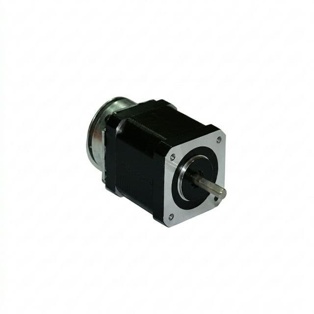
In a spring-applied brake, springs press an armature and friction disc together when the coil is unpowered. Energizing the coil attracts the armature against the springs to release the disc. The hub transfers torque between the disc and motor shaft. Air gap, hub geometry and mounting details depend on the selected design.
Oriental Motor's brake structure reference describes this holding principle and warns against using the described brake to stop a rotating load. That reference concerns servo brakes; it supports the operating principle, not a NEMA 17 performance rating.
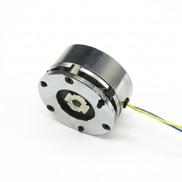
Holding versus stopping: Treat a holding-only brake as a stationary restraint. Check a separate permitted emergency-stop energy, speed and cycle rating before allowing engagement while moving. Driver deceleration can manage a commanded stop only while adequate power and control remain available. For total power loss, assess a rated stopping brake, counterbalance, energy reserve or separate restraint as the application requires.
3. Mechanical Sizing Physics: Gravity Backdrive Torque
For a direct-drive screw axis, use SI units:
F_gravity = m_total × g
T_backdrive = F_gravity × lead × eta_reverse / (2 × pi)
T_brake_min >= S × T_backdrive

g = 9.81 m/s²
lead: metres per revolution, not thread pitch on a multi-start screw
eta_reverse: reverse transmission efficiency, between 0 and 1
S: selected static design margin
The reverse-efficiency factor multiplies ideal torque because friction dissipates some of the energy released by the descending load. If reverse efficiency is unknown, use eta_reverse = 1 for conservative gravity-only screening; do not assume a favorable friction reduction. A self-locking screw needs separate evaluation.
For powered lifting, the forward efficiency appears in the denominator: T_lift = F_gravity × lead / (2 × pi × eta_forward), before acceleration and other loads. This is a different calculation. Both directions matter to motor selection.
For a direct-drive vertical belt, screen with T_backdrive = m_total × g × r_pitch, where r_pitch is the effective pulley pitch radius. For a reduction ratio i = motor revolutions / output revolution, ideal reflected gravity torque is T_output / i; include the actual transmission and its failure paths in final approval.
The examples use S = 2 solely as an explicit calculation assumption. It is not a universal standard or proof of compliance. Select a margin from the load uncertainty, permitted motion and exact brake's guaranteed minimum torque under temperature, wear and environmental conditions. A motor-shaft brake cannot retain a carriage after a downstream coupling or belt fails.
4. Flyback Suppression: Electrical Decay versus Mechanical Engagement
A brake coil stores magnetic energy. The switch-off circuit must dissipate or recover that energy without exceeding the coil, switch or insulation ratings. Texas Instruments' inductive-load application brief explains why a low-voltage freewheeling path demagnetizes more slowly than a higher-voltage clamp.
A simplified constant-inductance model for a clamp across the coil is:
L × di/dt = -(R × i + V_clamp)
E_initial = 0.5 × L × I_initial²

t_electrical = (L / R) × ln[(R × I_initial + V_clamp)
                            / (R × I_threshold + V_clamp)]
Here V_clamp is the magnitude of reverse voltage across the coil terminals, not necessarily the switch's drain-to-source clamp rating. I_threshold is the model's assumed current at which the spring can begin applying the brake. Real inductance varies with armature position; this electrical model cannot predict full holding torque by itself.
| Suppression topology | Electrical behavior | Required integration check |
|---|---|---|
| Freewheeling diode | Low reverse voltage; longer current decay relative to a higher clamp | Verify the complete engagement time is acceptable |
| Diode plus series Zener | Higher reverse voltage can shorten decay | Confirm orientation, pulse energy and switch voltage |
| Bidirectional TVS or MOV | Clamps at a device-dependent voltage | Check standoff, actual clamp voltage, tolerance and lifetime |
| Integrated active clamp | Driver dissipates or redirects stored energy | Follow its inductive-energy and repetition limits |
A plain diode in parallel with a higher-voltage suppressor can still dominate the recirculation path. A single ordinary TVS connected in its forward direction can also act like a freewheeling diode. Specify the complete circuit, including any suppressor already inside the brake or PLC output, rather than ordering a nominal “36 V clamp.” For a low-side switch and a clamp across the coil, switch stress can approach supply voltage plus the reverse coil clamp voltage and overshoot.
Measure time from the command to the required holding torque, including output delay, current decay and armature movement. There is no universal 15–25 ms or 80–150 ms brake response. To illustrate timing sensitivity only, an unsupported mass starting from rest under g = 9.81 m/s² travels s = 0.5 × g × t²: 1.96 mm in 20 ms, 12.26 mm in 50 ms, and 49.05 mm in 100 ms. A screw axis has reflected inertia and friction; a moving axis has initial velocity. These free-fall examples do not predict the machine's displacement or define an acceptable drop.
5. Visual Architecture & PLC Timing State Machine
The conceptual diagram shows the brake arrangement and a commanded start/stop sequence. Horizontal spacing is illustrative; obtain release and engagement times for the exact brake, wiring and operating conditions. The product photos show packaging, not an internal inspection or a verified timing test.
PLC sequence for a commanded start and stop
- Start: Enable the motor driver and allow sufficient holding torque to establish while the brake remains engaged. Energize the brake coil at its specified voltage. Wait the validated worst-case release time plus the chosen control margin, then issue motion commands.
- Stop: Decelerate the axis to rest. Maintain sufficient motor holding current, remove brake-coil power, and wait the validated engagement time plus margin before disabling motor current. Check that any automatic idle-current reduction does not undermine this overlap.
- Fault or total power loss: The above overlap may disappear when the motor supply collapses. Assess the actual power architecture, brake engagement at the resulting speed, available stopping energy and permitted travel. A PLC timer alone cannot preserve torque after its power source is lost.
Do not release a gravity-loaded brake before the motor can support the load. If brake feedback is available, define how the controller responds to a missing or inconsistent signal; coil voltage alone does not prove mechanical engagement.
6. Thermal Coupling & Rear Bearing Reliability
Use the selected coil's electrical data. As a specific catalog example, StepperOnline's spring-applied brake installation guide lists the SWB-01 for NEMA 17 at 24 V, 5 W and 0.25 N·m static holding torque. This does not rate every NEMA 17 brake or establish a complete motor assembly's load capacity.
For a hypothetical coil measuring 150 ohms at the stated temperature, P = V²/R = 24²/150 = 3.84 W. Resistance changes as the coil warms. With fixed resistance, a 10% voltage increase raises power by 21%; verify the actual permitted supply range.
Heat can conduct through the rear mounting into the motor and bearings. Coil watts alone do not determine a 20–35°C casing increase. Record ambient, enclosure ventilation, motor current, duty, mounting surface and stabilization criterion when checking the assembled unit.
- Insulation: Review the actual winding and brake-coil limits. A higher insulation class does not increase a bearing, magnet or housing limit. See NEMA 17 insulation classes and thermal selection.
- Bearings and lubrication: Obtain the installed bearing and grease temperature limits rather than assuming a bearing code or grease chemistry from frame size.
- Reduced-power release holding: Use a PWM economizer only if the brake manufacturer approves the waveform, pull-in duration and minimum hot-coil holding current. Do not assume that 30–40% voltage will keep every brake released; current ripple and suppression also affect behavior.
7. Mechanical Backlash & Linear Droop
A locked friction disc does not necessarily mean zero shaft movement. Hub clearance, shaft joints, screw/nut play and elastic deflection can all contribute to unpowered displacement. Obtain the actual brake's angular-play limit and a complete axis measurement; there is no universal 0.8–2° value.
For a direct-drive screw, h_backlash = theta_backlash / 360° × lead. An assumed 1.5° of angular play gives 0.0333 mm (33.3 micrometres) at 8 mm lead, or 0.0083 mm (8.3 micrometres) at 2 mm lead. These examples exclude all other sources of movement.
An absolute encoder can reveal displacement after power returns; it cannot prevent descent. An anti-backlash nut addresses its own interface, not every clearance in the brake and transmission. Specify allowable carriage movement directly and test it at the point where position matters.
8. Engineering Sizing Matrix: Six Reproducible Screening Cases
These are calculation inputs and results, not supplier configurations or maximum recommended payloads. All rows assume direct drive, gravity only, g = 9.81 m/s², no credit for friction, and S = 2. Motor acceleration torque, screw thrust bearings, belt strength, brake delay and stopping energy require separate checks.
| Transmission | Moving mass | Lead or pitch radius | Gravity torque at brake shaft | Minimum static brake torque at S = 2 | Separate selection check |
|---|---|---|---|---|---|
| Screw | 1.8 kg | 2 mm lead | 0.00562 N·m | 0.01124 N·m | Powered torque and screw speed |
| Screw | 1.8 kg | 8 mm lead | 0.02248 N·m | 0.04497 N·m | Engagement movement and nut play |
| Screw | 5 kg | 8 mm lead | 0.06245 N·m | 0.12490 N·m | Thrust path and acceleration |
| Screw | 10 kg | 8 mm lead | 0.12490 N·m | 0.24981 N·m | Minimum hot/worn brake torque |
| Belt | 1.8 kg | 6.366 mm radius | 0.11241 N·m | 0.22482 N·m | Belt retention and shaft load |
| Belt | 4.5 kg | 10 mm radius | 0.44145 N·m | 0.88290 N·m | Reduction or counterbalance |
Values are rounded from the equations in Section 3. The 10 kg screw case is close to a nominal 0.25 N·m brake rating and leaves essentially no allowance beyond the assumed factor; this arithmetic does not approve that combination. Use the supplier's guaranteed minimum torque at the specified conditions.
9. Worked Engineering Scenarios
Scenario A: Hypothetical pipetting Z-axis
Assume a 1.8 kg moving assembly and an 8 mm lead screw. With no credit for reverse friction, gravity torque is 1.8 × 9.81 × 0.008 / (2 × pi) = 0.02248 N·m. The example margin of two gives a minimum static target of 0.04497 N·m.
A nominal 0.25 N·m brake exceeds that static target, but selection still needs the guaranteed minimum torque, allowable movement, release voltage and power-loss response. Do not declare zero drift from the torque ratio: hub play, compliance and delay are separate effects. This is a calculation example, not a clinical installation record.
Scenario B: Hypothetical vertical belt gantry
Assume 4.5 kg on a 10 mm pitch-radius pulley. Gravity torque is 4.5 × 9.81 × 0.010 = 0.44145 N·m. A nominal 0.50 N·m brake gives a static ratio of only 1.13, below this example's target of two. A 3:1 ideal reduction lowers reflected torque to 0.14715 N·m and raises the nominal ratio to 3.40.
That reduction is an option to investigate, not a compliance finding. Verify gearbox strength, reverse efficiency, backlash, brake location and belt-failure consequences. Alternatively, a 2 mm lead screw gives a conservative gravity-only torque of 0.01405 N·m, but changes speed, powered torque and thrust-support requirements.
10. B2B Procurement & OEM Acceptance Checklist
Agree the acceptance record before buying production samples:
- Electrical definition: Brake model, rated voltage, permitted tolerance at the coil terminals, cold resistance, power, connector pinout and polarity. State the motor phase-current requirement separately.
- Static retention: Guaranteed minimum torque at agreed temperature, wear and contamination conditions; include the torque-test method and rejection limit.
- Timing and movement: Maximum release and engagement times with the supplied suppression network, and maximum carriage displacement during the specified stop and power-loss tests.
- Suppression circuit: Identify internal protection, required external components, switch ratings, pulse energy and repetition limits. Supply the wiring diagram used for qualification.
- Thermal compatibility: Record assembled-unit temperatures at maximum ambient and duty; check motor, brake, bearing and lubricant limits separately.
- Mechanical interface: Rear shaft and mounting drawing, total CAD envelope, hub play, shaft retention, air-gap/service instructions and the separate axial-thrust support path.
- Harness and fault behavior: Confirm cable routing, strain relief, encoder-noise immunity, brake feedback if supplied, and behavior on a broken conductor or loss of each supply.
- Life and commercial handoff: Specify an application-derived cycle target, load/speed profile, maintenance interval, traceable sample report, drawing revision, sample/production quantities and destination terms. Static-cycle life is not an emergency-stop energy rating.
Use the NEMA 17 OEM RFQ checklist to organize the drawing, quantity split and acceptance attachments. Send the completed load and timing requirements with your quotation request.
11. Technical Frequently Asked Questions (FAQ)
Why do vertical NEMA 17 stepper axes drop when motor power is switched off?
Motor holding torque decays with phase current after power removal. Residual detent torque and transmission friction may remain, but they do not establish a guaranteed holding capacity. A backdrivable axis can descend if gravity exceeds that resistance; a self-locking screw may behave differently. Validate the complete transmission.
What is the difference between a dynamic brake and a holding brake on a NEMA 17 motor?
A holding brake secures a stationary shaft. Dynamic stopping also requires a permitted stopping-energy and wear rating. Do not assume a holding-only brake can arrest a moving load on power loss; obtain the exact brake rating and provide a suitable stopping or load-restraint system.
How does a flyback diode affect vertical-axis sag during power loss?
A freewheeling diode permits brake-coil current to recirculate after switch-off, which can delay spring engagement compared with a higher-voltage clamp. Total engagement time includes electrical decay and mechanical movement. Measure the actual coil, suppression circuit and load; no universal delay or drop distance applies.
How can engineers reduce inductive switch-off delay?
Use the brake and output-stage manufacturers' approved suppression network. A suitable TVS, diode-plus-Zener network, MOV or active clamp can speed current decay, but must meet voltage, energy and repetition limits. Faster electrical decay does not eliminate mechanical engagement time or prove the axis is safe.
How much heat does an electromagnetic brake add to a NEMA 17 motor?
Use the selected coil rating. For example, StepperOnline lists its SWB-01 NEMA 17 spring-applied brake at 24 V and 5 W. This is coil power, not a motor temperature-rise prediction. Validate the assembled motor, brake and bearings at the intended ambient temperature and duty cycle.
What PLC sequence prevents sag during a commanded start and stop?
Start: enable the motor, establish holding torque, energize the brake coil, wait the validated release time, then issue motion commands. Stop: decelerate to rest, retain sufficient motor holding current, remove brake-coil power, wait the validated engagement time plus margin, then disable the motor. Total power loss needs a separate validated response.
12. Sources & Engineering References
Sources checked November 02, 2026. These references support the identified principles or model data; none supplies a universal NEMA 17 payload limit. The equations, rounded examples and acceptance framework are the analysis in this guide. No measured brake performance is claimed.
- Oriental Motor — Electromagnetic Brake Structure and Service Life (Servo Motor). Spring-applied position-holding principle and the restriction against stopping a rotating load with the described holding brake. Servo-brake reference, not a NEMA 17 timing specification.
- StepperOnline — How to Install a Spring-Applied (Power-Off) Brake on a Stepper Motor. SWB-01 model example and rear-shaft/mounting requirements; its 24 V, 5 W and 0.25 N·m figures apply to that brake. The guide distinguishes spring-applied and permanent-magnet designs.
- Texas Instruments — SNVAA45: Faster Switching of Large Inductive Loads in Digital Output Modules. Freewheeling versus higher-voltage clamping, discharge-energy handling and switching constraints. General inductive-load reference, not a mechanical brake engagement guarantee.
13. Request an Engineering Review or Custom Brake-Motor RFQ
Contact our engineering team with moving mass, screw lead or pulley radius, gearing, maximum speed, permitted power-off movement, ambient temperature and available supply voltages. Include your CAD envelope and sample/production quantities so the review can address the complete motor-brake assembly and its acceptance tests.
Explore related technical NEMA 17 motor resources and radial and axial bearing load limits when defining the transmission and thrust-support requirements.
Author

Carl Ostermann - Principal Electromagnetic Drive Specialist
Principal Electromagnetic Drive Specialist specializing in high-torque-density motor topologies, slotless/frameless stator-rotor thermal management, and industrial motion control.
More Posts
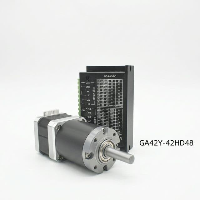
NEMA 17 Customization: Shaft, Connector, Gearbox, and Lead Screw
What OEM buyers should define early when requesting customized NEMA 17 assemblies for production programs.
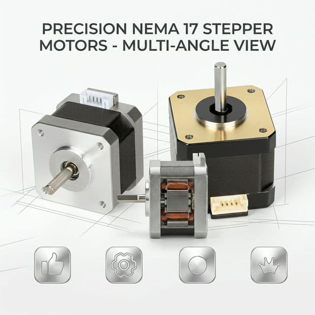
NEMA 17 Integrated Motors: BOM Reduction & TCO Analysis for OEMs
Learn how integrated NEMA 17 stepper motors reduce BOM complexity and TCO for OEMs, with sourcing checks, TCO inputs, and RFQ questions for global buyers.
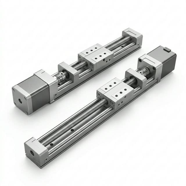
NEMA 17 Hybrid Linear Stepper Actuators: External vs. Non-Captive vs. Captive Sizing & Procurement Guide
Compare NEMA 17 linear actuators: External, Non-Captive, and Captive. Check thrust, backdriving, duty cycle, and backlash; prepare an OEM RFQ with clear inputs.